Einstellungen
General
- User interface
- Storage location
- iProperties
- Displayname
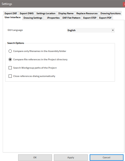
Language
On this tab, the language of the user interface can be changed. Currently, German and English are supported languages. In order for the change to affect all parts of the program (including Inventor ribbon/buttons), the add-in needs to be unloaded and reloaded (or restarting Inventor will have the same effect).
Search options
Compare only file names in the assembly folder
With this option, the drawings will only be searched in the folder where the active assembly file is located. If the drawings are saved in a different folder, they will not be found with this search option. However, if the condition is met, this function is preferable to the alternative search function, as the search can be completed much faster this way.
Compare file references in the project directory
This option is more comprehensive but also significantly more time-consuming. It involves first finding all drawing files (IDW or Inventor DWG, depending on the set drawing file format) in the current Inventor project. Then, the file references in the drawings are compared with the components of the active assembly, ensuring that all drawings for all components of the assembly are found in the project. Depending on the size of the assembly and the number of drawings, this process can take some time. The project-based search operation is logged in a separate sub-dialog.
Search project's workgroup search paths
This option can be selected in addition to the project search. The project search scans the project's root directory and all its subfolders recursively. With this additional option, you can instruct the program to also search the project's workgroup search paths for drawings. This option is particularly useful in cases where the drawings are stored in a separate folder structure on a different drive, for example. If your drawings are located in a folder within the project, you do not need to select the workgroup search option.
Automatically close reference dialog
This option enables the automatic closing of the reference dialog that is displayed during the search for references. With this option, you don't need to click the "Next" button to proceed.
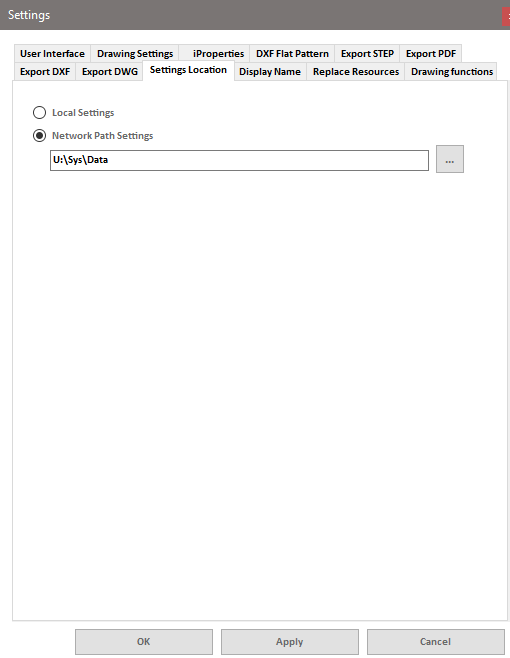
Here you can specify whether the settings should be sourced from the local data directory in the program's installation folder (usually the C:\ProgramData\Mensch und Maschine\Multitool_For_Inventor\Data folder) or if the settings should be sourced from another folder. This other folder could be a central network path in your company network (UNC path or network drive). If the settings are to be sourced from another folder, the program will check if the selected folder contains the necessary files and reload all settings from the files in the selected folder.
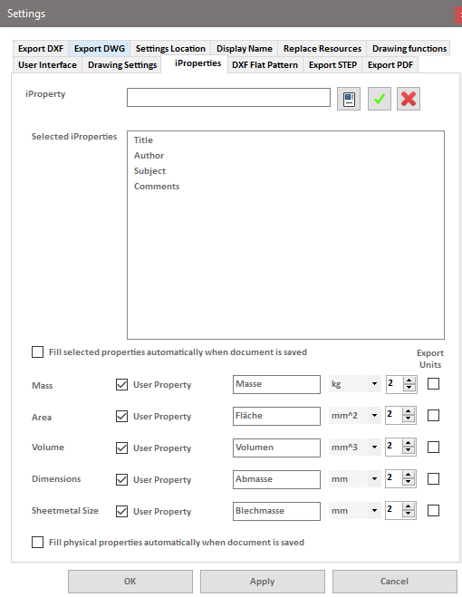
On this tab, you can define a list of relevant iProperties. You can use the "+" and "x" buttons to add the name in the 'iProperty' text field as a new item to the list or delete the selected iProperty from the list.
The list defined here is used by the functions Manage iProperties and Transfer iProperties.
The 'iProperty' text field has an autocomplete function that suggests the names of all standard iProperties.
The option "Automatically enter properties when saving" causes the properties to be set automatically according to the default settings without displaying the dialog. In this case, any non-existent properties will also be created automatically.
The physical properties such as mass, area, volume, dimensions, and sheet metal mass are entered into the specified iProperties if selected. If the iProperties do not exist, they will be created automatically. The selection fields under "Export Unit" determine whether only the value(s) themselves or the value(s) with unit(s) are entered into the iProperty when recording the respective iProperty value(s). In the function Transfer iProperties the physical properties will be displayed on the Model Properties side if they are selected here.. You can then optionally transfer them to corresponding iProperties in the drawing. For each of these properties, you can specify the unit of measurement and the number of decimal places to display. You can also set the name under which the property should be displayed or saved.
With the option "Automatically enter physical properties when saving," you instruct the program to automatically save the physical properties as iProperties when saving the Inventor document (or update their values if the properties already exist).
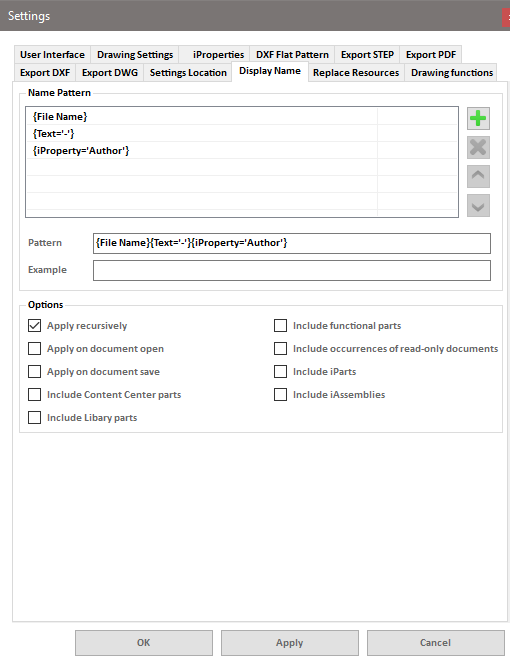
This tab contains the settings for the "Display Names" function.
Naming convention
The "+" button adds filename, filename extension, fixed text, or iProperty values as elements to the naming scheme. The "x" button removes the selected naming element from the list. The up/down buttons move the elements within the list.
Schema: The composite list of naming scheme elements.
Example: An example of the resulting name based on the naming scheme, using the properties of the currently active Inventor document.
Options
Apply recursively: Only relevant for Inventor assemblies. If this option is enabled, the program applies the naming rules not only to the assembly document itself but also to the sub-components of the model, including sub-assemblies and their components.
Apply on open: The naming rules are applied when opening an Inventor document.
Apply on save: The naming rules are applied when saving an Inventor document.
Apply to Content Center parts: The naming rules are applied to Content Center parts.
Apply to library parts: The naming rules are also applied to components whose documents are located in one of the library paths of the active Inventor project.
Apply to functional parts: The naming rules are also applied to parts generated by the Inventor tools such as "Tube/Pipe," "Cable & Harness," or "Design Accelerator."
Apply to read-only parts: The naming rules are also applied to components whose documents are read-only (e.g., local copies of Vault files that are checked out and released).
Apply to iParts: The naming rules are also applied to iPart and iPart Factory parts.
Apply to iAssemblies: The naming rules are also applied to iAssembly and iAssembly Factory assemblies.
Export options
- DXF Flat pattern
- STEP export
- PDF export
- DXF export
- DWG export
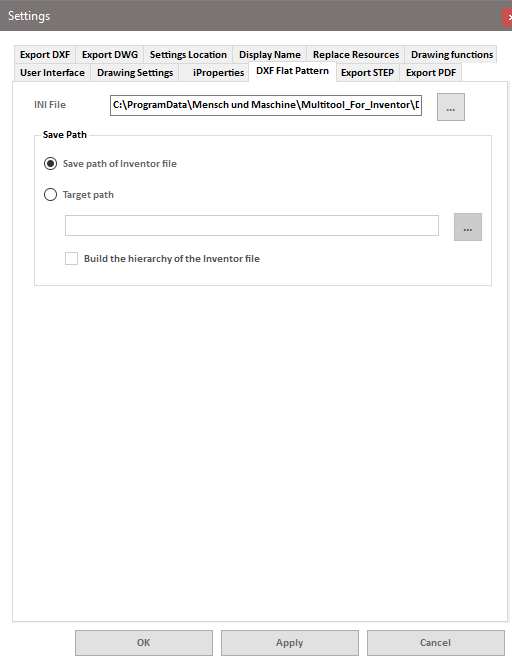
These settings are related to exporting the DXF flat pattern based on an assembly or a part. The options for converting IDW/Inventor DWG drawings to the DXF format are located on the "Export DXF" tab (see further below).
In the DXF flat pattern settings, you can specify the settings to be used in the form of an INI file.
Additionally, you can determine whether the DXF files will be saved in the same path as the respective model file or in a predefined folder. In the latter case, the program can also optionally replicate the folder structure of the model files in this output folder.
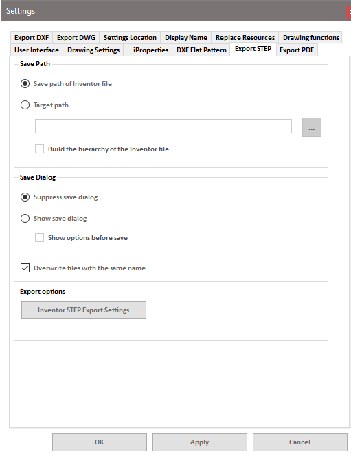
In this tab, you can configure the settings for the STEP export of assemblies and parts.
Storage location
The converted model file can be saved either at the same location as the Inventor model file or in a custom destination folder.
If the "Destination Folder" option is chosen, you can also specify whether the file will be saved directly in this destination folder or if the program should replicate the folder hierarchy of the model file in the destination folder. The converted file will then be saved in the corresponding subfolder of the hierarchy.
Save dialog
By default, the Inventor save dialog for individual STEP files is suppressed. However, it is possible to optionally display a save dialog for each file to specify the storage location and file name.
Additionally, it can be configured to display the "Options" dialog separately for each file (similar to the options of "Save Copy As" in Inventor).
Existing STEP files with the same name are overwritten without prompt by default. However, this behavior can be optionally changed so that the program prompts for each existing file, asking whether it should be overwritten.
Export options
The "Inventor STEP Export Settings" button opens a dialog where you can define the options for file export (the same settings as in the "Options" dialog for the Inventor "Save Copy As" command).
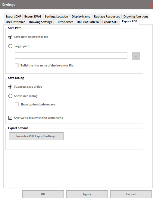
In this tab, you can configure the settings for the PDF export of drawings.
Storage location
The converted file can be saved either at the same location as the Inventor drawing or in a custom destination folder.
If the "Destination Folder" option is chosen, you can also specify whether the file will be saved directly in this destination folder or if the program should replicate the folder hierarchy of the drawing file in the destination folder. The converted file will then be saved in the corresponding subfolder of the hierarchy.
Save dialog
By default, the Inventor save dialog for individual PDF files is suppressed. However, it is possible to optionally display a save dialog for each file to specify the storage location and file name.
Additionally, it can be configured to display the "Options" dialog separately for each file (similar to the options of "Save Copy As" in Inventor).
Existing PDF files with the same name are overwritten without prompt by default. However, this behavior can be optionally changed so that the program prompts for each existing file, asking whether it should be overwritten.
Export options
The "Inventor PDF Export Settings" button opens a dialog where you can define the options for file export (the same settings as in the "Options" dialog for the Inventor "Save Copy As" command).
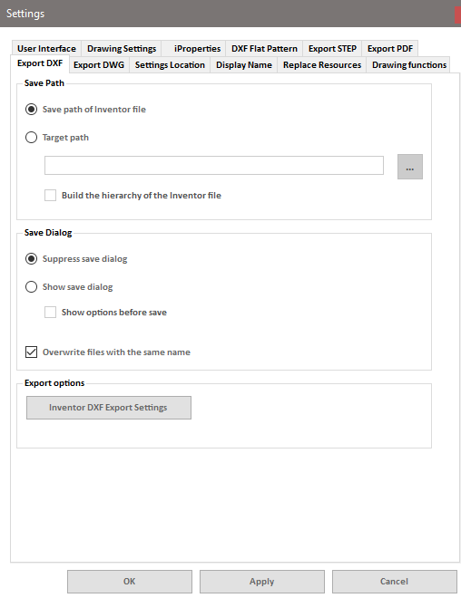
These settings pertain to saving IDW or Inventor DWG files as DXF files. The settings for creating DXF flat patterns from sheet metal parts are located in the "DXF Flat Pattern" tab (mentioned earlier).
In this tab, you can configure the settings for the DXF export of drawings.
Storage location
The converted file can be saved either at the same location as the Inventor drawing or in a custom destination folder.
If the "Destination Folder" option is chosen, you can also specify whether the file will be saved directly in this destination folder or if the program should replicate the folder hierarchy of the drawing file in the destination folder. The converted file will then be saved in the corresponding subfolder of the hierarchy.
Save dialog
By default, the Inventor save dialog for individual DXF files is suppressed. However, it is possible to optionally display a save dialog for each file to specify the storage location and file name.
Additionally, it can be configured to display the "Options" dialog separately for each file (similar to the options of "Save Copy As" in Inventor).
Existing DXF files with the same name are overwritten without prompt by default. However, this behavior can be optionally changed so that the program prompts for each existing file, asking whether it should be overwritten.
Export options
The "Inventor DXF Export Settings" button opens a dialog where you can define the options for file export (the same settings as in the "Options" dialog for the Inventor "Save Copy As" command).
Please note that the settings in this dialog need to be saved as an INI file to persistently retain them (even after ending the Inventor session).
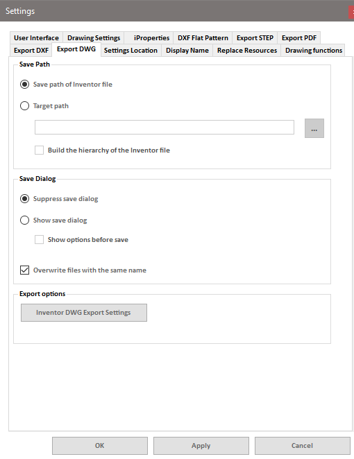
In this tab, you can configure the settings for the DWG export of drawings.
Storage location
The converted file can be saved either at the same location as the Inventor drawing or in a custom destination folder.
Please note that this option can be problematic when exporting Inventor DWG drawings. The generated AutoCAD DWG drawings will have the same name as the original Inventor DWG files by default. However, this issue can be bypassed using the file naming options in the Export Ribbon Panel of the Inventor Multitool Ribbons, located next to the export commands.
If the "Destination Folder" option is chosen, you can also specify whether the file will be saved directly in this destination folder or if the program should replicate the folder hierarchy of the drawing file in the destination folder. The converted file will then be saved in the corresponding subfolder of the hierarchy.
Save dialog
By default, the Inventor save dialog for individual DWG files is suppressed. However, it is possible to optionally display a save dialog for each file to specify the storage location and file name.
Additionally, it can be configured to display the "Options" dialog separately for each file (similar to the options of "Save Copy As" in Inventor).
Existing DWG files with the same name are overwritten without prompt by default. However, this behavior can be optionally changed so that the program prompts for each existing file, asking whether it should be overwritten.
Export options
The "Inventor DWG Export Settings" button opens a dialog where you can define the options for file export (the same settings as in the "Options" dialog for the Inventor "Save Copy As" command).
Please note that the settings in this dialog need to be saved as an INI file to persistently retain them (even after ending the Inventor session).
Drawing options
- Drawing functions
- Drawing settings
- Update Resources

This tab contains the update settings for the two drawing functions, namely Fit List and Inspection Dimension Table.
Automatically on change and save: If this option is enabled, the list or table will be automatically updated whenever a dimension is modified, deleted, or added, and when the drawing document is saved.
Manual only (Update button): If this option is enabled, the list or table will be updated only when the corresponding button in the Inventor Ribbon is clicked.
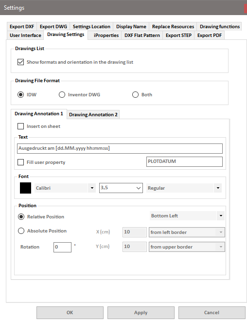
Drawing list
Here you can specify whether the sheet format and orientation should be displayed in the file list in the assembly print. This option is optional because reading this information requires opening the drawings. If this information is not necessary, the search for drawings will be faster.
Drawing file format
You can specify whether the program searches for drawings with the ".idw" file extension, the ".dwg" file extension, or both. Please note that the ".dwg" extension specifically refers to Inventor DWG drawings, and the program is not designed to work with AutoCAD drawings.
Drawing annotation 1 and drawing annotation 2
You can define two different temporary drawing labels, which will be inserted as text boxes into the sheets before printing and removed after printing. Label 1 is currently fixed as a date/time stamp using the format "Printed on [dd.MM.yyyy hh:mm:ss]". The text in Label 2 is customizable.
The "Enter as user property" option writes the text into an iProperty, which will be automatically created if it doesn't already exist.
The "Place on drawing" checkbox determines whether the respective text box is used. For both text boxes, you can set the font and size (in millimeters) and choose a text color.
The text boxes can be inserted either in predefined relative positions (bottom left, bottom right, top left, top right, centered) or in absolute positions. The absolute positions are defined as the X distance from the left or right edge of the drawing and the Y distance from the top or bottom edge of the drawing.
Additionally, you can specify a rotation angle for the text box (default is 0° - no rotation).
Automatically on Open: If this option is enabled, the activated functions (replace title blocks, replace borders, revision tables) will be automatically executed when an Inventor drawing file is opened.
Automatically on Save: The functionality is similar to the one described above, but with this option, the function is triggered when the file is saved.
Both functions only apply to visible open drawing files. If a drawing is opened invisibly, the command will not be executed.
Titleblock definitions
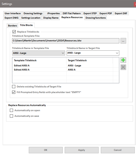
Replace Title Blocks: If this option is enabled, the program replaces title blocks in the drawing template file. Click the "..." button to select the template file containing the title block definitions.
Title Block Name Mapping: A list of name pairs to map title block names in the template drawing to the corresponding title block names in the target drawings. If the title blocks in your (new) template have different names, you can use this list to define rules for replacing the old title blocks with the new ones.
Title Block Name in Template / in Target File: The dropdown menu for the template title block contains the names of all title block definitions in the selected template file. The combobox for the target file contains the names of all title block definitions in the currently active Inventor drawing. If the active document is not a drawing, the dropdown selection will be empty, but you can manually enter the name of the target title block that will be replaced with the associated title block from the template when the function is executed.
"+" Button: Adds the combination of the template and target title block names to the list of displayed name pairs.
"x" Button: Removes the selected list entry from the list.
Delete Existing Title Blocks in the Target File: If this option is enabled, all existing title block definitions in the target file will be deleted. If the option is disabled, only definitions in the target file will be replaced by identically named definitions from the template. Definitions for which there is no identically named counterpart in the template will remain unchanged.
Fill Requested Input Fields with Placeholder Text "LEER": Title blocks with requested inputs cannot be automatically filled with meaningful values. There are two options here:
- If the option is enabled, the title block will be replaced, and "LEER" will be inserted as a placeholder text for all requested inputs.
- If the option is disabled, the new title block definition may be transferred to the drawing, and the existing title block to be replaced will be removed from the sheets, but the new title block will not be inserted on the sheets. You will need to manually insert the title block using Inventor functions and enter the desired values for the requested inputs through the user interface.
Borders
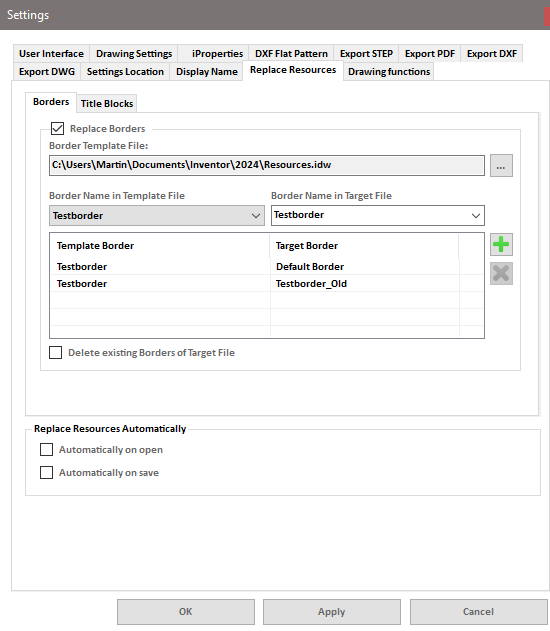
Replace Borders: If this option is enabled, the program replaces borders in the drawings. The additional options under "Replace Borders" work analogously to the options described above for the "Replace Title Blocks" function.